- Phone / WhatsApp:+86 157 0677 9792
- sales@toonice.com
-
English



How to Size and Select a Distribution Transformer for Your Project
Aug 05,2026
Selecting the right transformer rating is an important part of any power distribution project. An undersized transformer may operate at excessive temperatures, experience greater voltage drop, and have a shorter service life. Oversizing, on the other hand, increases initial cost and can result in unnecessary no-load losses.
Proper transformer sizing requires more than simply adding up the connected loads. This article outlines a practical five-step process used by Toonice engineers to determine a suitable transformer rating based on actual load requirements and operating conditions.
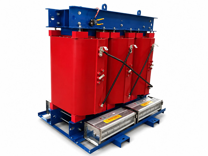
Step 1: Define the Load Profile
Distribution transformer sizing begins with the loads, and a transformer rating is meaningless until the real demand behind it is understood.
Connected Load versus Demand
The connected load is the sum of the nameplate ratings of every device that can be switched on, including motors, lighting, HVAC units, pumps, and control equipment.
Demand is the power actually drawn at a given moment, and almost no facility runs every device at full rating at the same time. Using the connected load directly therefore produces an oversized transformer.
The relationship between the two is captured by the demand factor, which is the ratio of expected peak demand to connected load. A workshop full of intermittent machines behaves very differently from a process line that runs continuously, and typical values vary widely by application.
The safest input is measured data from existing operations; where that is unavailable, equipment datasheets and the operating schedule give a defensible estimate.
Growth Allowance
Loads rarely stay flat over the working life of a transformer. A new production line, an expanded warehouse, or added EV charging points can push demand well beyond the original design, and adding a growth allowance at the sizing stage is far cheaper than replacing a transformer early.
Planning margins are a judgment call rather than a fixed rule. A common planning figure is 10 to 20 percent of the calculated demand, depending on the project horizon and how certain the load forecast is.
When in doubt, our engineers prefer a modest allowance plus reasonable overload headroom, because the cost difference between adjacent standard ratings is small compared with a forced upgrade.
Step 2: Convert kW to kVA
Distribution transformers are rated in kVA rather than kW, and understanding why is central to any distribution transformer sizing exercise. The unit must physically handle the apparent power of the load, which includes both the useful power and the reactive component that motors and other inductive equipment require.
The basic conversion is: kVA = kW ÷ Power Factor: For example, an 800 kW load operating at a power factor of 0.8 requires 1,000 kVA of apparent power. Power factor varies with the type of load.
Resistive equipment, such as electric heaters, typically operates close to 1.0, while motors, compressors, and other inductive loads generally have lower values. Where possible, use the power factor specified in the equipment data or measured under normal operating conditions.
Transformer sizing should therefore be based on the expected operating power factor rather than an assumed value. If power factor correction is planned, its effect can also be included when evaluating the required transformer capacity.
Step 3: Check Voltage and Vector Group
Transformer selection involves more than the kVA rating. The primary and secondary voltages, system frequency, and vector group must also match the network requirements.
IEC 60038 provides reference values for standard system voltages. Distribution networks commonly use primary voltages such as 11 kV, 22 kV, or 33 kV, while 400 V is widely used on the low-voltage side in IEC-based three-phase systems.
Actual voltage levels vary by country and utility, so the network voltage should always be confirmed before specifying the transformer.
The vector group defines the winding connections and phase displacement between the high- and low-voltage sides. Dyn11, for example, uses a delta-connected HV winding and a star-connected LV winding with neutral brought out, with a 30° phase displacement.
The required vector group depends on the network configuration and is particularly important when transformers operate in parallel. Always check the utility requirements and existing system configuration before finalizing the specification.
Step 4: Choose Cooling and Enclosure Fit
With the electrical parameters defined, attention turns to where the transformer will live and how it will be cooled.
Indoor installations place the unit inside a building or substation room, where ventilation becomes the main concern. A transformer converts a small share of its throughput into heat, and that heat has to leave the room, so indoor units need enough airflow, and confined spaces may require additional cooling measures.
Outdoor installations face weather instead of walls, and enclosures must handle rain, dust, and temperature swings.
The choice between dry-type transformers and oil-immersed transformers is closely tied to the installation environment. Oil-immersed units are common in outdoor substations and utility applications, while dry-type units are frequently chosen for indoor and building-integrated installations.
Each technology has its own ventilation and enclosure requirements, and the product pages cover the practical differences in more detail.

Altitude also plays a role. Cooling depends on air density, which drops at higher elevations, so a transformer installed at altitude may need to be derated to stay within its temperature limits.
The general principle is well established in IEC 60076, and the exact derating factor depends on altitude and design, so it should be confirmed on the datasheet for the specific model.
Step 5: Compare Losses and Efficiency
Transformer efficiency is mainly influenced by two types of loss: no-load loss and load loss.
No-load loss, also known as core or iron loss, is present whenever the transformer is energized, regardless of the connected load. Load loss, often referred to as copper loss, varies with load current and increases approximately with the square of the current.
For transformers that remain energized at light load for long periods, no-load loss can have a significant impact on lifetime energy consumption.
Loss values vary with transformer rating, core material, winding design, and manufacturing technology. Rather than relying on general efficiency figures, compare the guaranteed no-load and load losses provided by the manufacturer.
The IEC 60076 series provides the relevant framework and test requirements for evaluating transformer performance.
When selecting a transformer, consider both the initial cost and expected energy losses over its service life. For installations with long operating hours, a more efficient design may justify a higher initial investment through lower operating costs.
Worked Example
A short example makes the workflow concrete. The figures below are assumptions for illustration only; every real project should use its own measured or estimated values.
Assume a facility with an expected peak demand of 800 kW at a power factor of 0.8, with no plans for power factor correction.
The kVA calculation comes first: 800 kW divided by 0.8 gives 1000 kVA. Adding a 20 percent growth allowance gives 1200 kVA of required capacity, and the nearest standard rating above that figure is 1250 kVA in this example.
The selected unit would then be checked against the site voltage (for example 11 kV primary, 400 V secondary), the vector group, and the installation environment before the final specification is issued.
The same five steps scale up and down: a small commercial building might land on a unit of a few hundred kVA, while an industrial campus can reach several MVA. The method stays identical, and only the numbers change.
FAQ
Q What is the difference between kW and kVA in distribution transformer sizing?
kW is the real power that loads actually consume, while kVA is the apparent power the transformer must carry. The two are related by the power factor: kVA equals kW divided by power factor. Because inductive loads draw reactive power, the kVA rating is always equal to or higher than the kW demand.
Q Can a distribution transformer run at full load continuously?
A transformer can be designed to operate at its rated load, but continuous operation at the limit leaves no room for load peaks, ambient temperature effects, or growth. Standard practice is to size with a margin so the unit runs below its rating in normal conditions. Overload capability varies by model and cooling class, so the datasheet is the reference for any sustained overload question.
Q How do the installation requirements differ between oil-immersed and dry-type transformers?
The decision is driven mainly by the installation environment: outdoor utility-style locations commonly use oil-immersed units, while indoor and building-integrated projects frequently use dry-type units. Fire safety, moisture, ventilation, and maintenance access all play a part. Our transformer range covers both technologies, and a sizing review will confirm which fits the project.
Conclusion
Transformer sizing depends on more than the calculated load. Voltage requirements, load profile, installation conditions, future capacity, and efficiency all need to be considered before the final rating is selected.
Toonice supports distribution transformer projects from initial sizing through equipment specification. If you are planning a new installation or reviewing an existing design, send us your load data and site requirements. Our engineering team can help confirm the appropriate transformer rating and provide the calculations needed for your project.

--- END ---

MV & LV Equipment Manufacturer · Wenzhou, China
COMPANY
PRODUCTS
INDUSTRIES