- Phone / WhatsApp:+86 157 0677 9792
- sales@toonice.com
-
English



Low-Voltage Switchgear Cabinets: Types and Applications
Sep 15,2026
A low-voltage switchgear cabinet is where the distribution of a site is organized. Incoming feeders, outgoing feeders, bus couplers, motor starters, and metering are housed in the same structure, and the arrangement has to allow each circuit to be operated, protected, and maintained without disturbing the rest.
The duties vary widely, so the cabinets are not interchangeable. A board that feeds lighting and socket circuits in a commercial building is a different problem from a board that starts and protects motors in a process plant, even when the voltage and current values look similar.
That difference shows up in the enclosure long before it shows up in the price. Withdrawable units need more depth and more mechanical structure than fixed units, motor control adds devices and control wiring to each compartment, and a higher fault rating adds busbar and barrier.
This article covers the decisions that shape the specification: withdrawable or fixed functional units, the difference between main and distribution busbar ratings, short-circuit withstand, degree of protection, and internal separation.
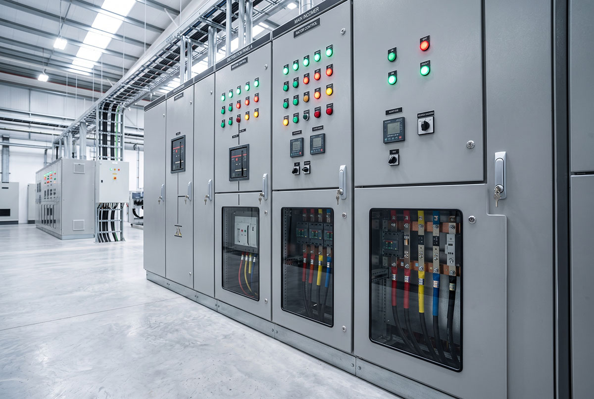
Withdrawable and Fixed Functional Units
The functional unit is the part of the cabinet that does the work on one circuit. In a withdrawable design it can be moved between service, test, and isolated positions without de-energizing the board, so a single feeder can be taken out of service and worked on while everything else keeps running.
That matters where availability is the main concern. Paying for withdrawable units in a board that is rarely switched is harder to justify than paying for them in a board that feeds a continuous process.
Fixed units are simpler and cheaper, and they suit installations where outages can be planned and the switching duty is low. The trade-off is that maintenance on a fixed unit usually means working on a de-energized section rather than sliding a spare unit into place.
Busbar Current and Short-Circuit Ratings
Two busbar ratings appear on a low-voltage datasheet, and they describe different parts of the same board. The main busbar carries the total current of the installation, while the distribution or vertical busbar feeds the individual functional units.
On a published MNS configuration, the main busbar is rated for a maximum operating current of 5000 A, and the distribution busbar is limited to 1000 A. That gap is normal, and it explains why the current available at the main busbar is not available at every feeder at the same time.
Short-circuit ratings follow the same split. The main busbar on that configuration is published at a rated withstand current of 100 kA for 1 s with a peak withstand of 200 kA. The distribution busbar is published at a peak current of 105 kA over 0.1 s in the standard version and 176 kA over 0.1 s in the reinforced version.
Insulation and operating voltages sit above the working voltage of the system. The MNS configuration is published with a rated insulation voltage of 660 V (1000 V) and rated operating voltages of 380 V and 660 V.
The GCK withdrawable range is published at 380, 400, 415, and 660 V operational, with insulation up to 1000 V, rated current up to 4000 A, and a rated short-time withstand current up to 50 kA for 1 s. Both ranges are published at 50 or 60 Hz, which allows the same construction to be applied in different regions.
Fault Level and Short-Circuit Withstand
The short-time withstand rating is the board’s ability to carry a fault current without being destroyed. It is set by the fault level that the upstream transformer can deliver at the point of installation, and it has to be checked against that value rather than against the continuous current rating.
The duration in the rating matters as much as the current. Values are published for a stated time, commonly 1 s or 0.1 s, and the protection has to clear the fault inside that window. A board with the right peak value and too short a withstand time will still be damaged if clearing is slow.
For motor control duty, the coordination is more demanding. The starter, the protection device, and the upstream breaker all act on the same fault, and their settings have to be checked together rather than selected one at a time.

Degree of Protection and Internal Separation
Degree of protection describes what can enter the enclosure. On the MNS range, IP30 protects against solid objects larger than 2.5 mm and IP40 against objects larger than 1.0 mm, referenced to IEC 529 and DIN 40050. Both are indoor ratings, and neither claims protection against water.
The GCK range is published at IP30 or IP40 according to the project requirement. Where a cabinet is installed in a dusty area or near washdown, the enclosure rating is the first item to confirm, because it affects ventilation, sealing, and the internal temperature.
Internal separation is a separate decision from the enclosure rating. It determines how much of the board stays live when one compartment is opened, and it is normally specified as a form of internal separation rather than chosen from a catalog. On the GCK range that form is project-specific, with IEC 61439-1 and IEC 61439-2 as the applicable standards.
Cable entry has to be settled at the same time. Top and bottom entry are both offered, and the choice affects the layout of the room, the routing of the incoming cables, and the space needed above and below the cabinet.
Where Motor Control Changes the Choice
A cabinet that also starts motors is no longer only a distribution board. Motor control center duty adds starters, contactors, overload protection, and control wiring, and the functional units are usually withdrawable so that a starter can be replaced without a long outage.
The GCK range is published for power distribution and motor control applications, with incoming feeder, outgoing feeder, motor control, bus coupler, and metering and monitoring configurations set by the project. The same structure can therefore serve a distribution board and a motor control center, provided the ratings are checked for both duties.
The difference shows up in the design margin. A motor control center carries more devices, more control wiring, and more heat per functional unit than a distribution board of the same current rating, so ventilation and separation have to be considered earlier in the design.

Documentation and Factory Testing
Routine inspections and tests are completed before shipment in accordance with IEC 61439-1, IEC 61439-2, and the project specification. The documentation package typically includes the single-line diagram, general arrangement drawing, technical datasheets, and routine test records.
These documents form part of the switchgear specification. The general arrangement drawing confirms cabinet dimensions and layout, the single-line diagram defines the circuit arrangement, and the test records document the checks completed before dispatch.
Key design inputs should be fixed before production begins. System voltage, rated current, feeder arrangement, motor control requirements, and short-circuit ratings all influence the busbar design, compartment layout, and equipment selection.
Late changes can affect several parts of the design at once. A revised feeder rating or an additional motor circuit may require changes to the busbars, internal layout, drawings, and test requirements. Defining the electrical scope early helps avoid unnecessary redesign and delays before shipment.
Conclusion
Low-voltage switchgear should be selected around the way the installation will operate and be maintained. Withdrawable units are useful where circuits need to be serviced with minimal interruption, while fixed units are often sufficient where planned outages are acceptable.
Electrical ratings then need to match the system itself. Busbar current, short-circuit withstand, and enclosure protection all have to reflect the load, fault level, and site conditions. Internal separation, cable entry, and documentation can then be defined around those requirements.
In practice, reliable switchgear selection comes from matching the cabinet to the electrical duty, maintenance strategy, and installation environment. The product type matters, but it only makes sense when the underlying system requirements have been defined first.
Need assistance defining the right specifications for your project? Contact our technical engineering team today to discuss optimized low-voltage switchgear solutions.

--- END ---

MV & LV Equipment Manufacturer · Wenzhou, China
COMPANY
PRODUCTS
INDUSTRIES