- Phone / WhatsApp:+86 157 0677 9792
- sales@toonice.com
-
English



Power Factor Correction with Capacitor Banks: Principles and Applications
Aug 10,2026
Low power factor can increase electricity costs, particularly for industrial facilities with large motor and inductive loads. Depending on the utility tariff, poor power factor may result in additional charges or higher demand costs, even when actual energy consumption remains unchanged.
Power factor correction addresses this by reducing the reactive power drawn from the supply. Capacitor banks are one of the most common solutions, helping improve power factor, reduce current in the distribution system, and make better use of existing electrical capacity.
This article explains how capacitor banks work and where they can provide practical benefits in an industrial power system.
What Power Factor Means in Simple Terms
In an AC power system, real power (kW) is the power used to perform useful work, such as driving a motor or heating a furnace. Many inductive loads, including motors and transformers, also require reactive power (kVAR) to establish the magnetic fields needed for operation.
The combination of real and reactive power determines the apparent power (kVA) supplied by the electrical system.
Power factor is the ratio of real power to apparent power:
Power Factor = kW ÷ kVA
A power factor close to 1.0 indicates that the available electrical capacity is being used efficiently. When power factor is low, more current is required to deliver the same amount of real power. This is common in industrial facilities with significant motor, transformer, compressor, or other inductive loads.
Low power factor also affects the upstream electrical network. Generators, transformers, switchgear, and cables must carry the total current, including the reactive component. Higher current increases system loading and losses, which is why some utilities apply power factor penalties or base demand charges on kVA rather than kW.
Where Low Power Factor Comes From
Low power factor almost always traces back to inductive loads. Motors are the biggest contributors, because every induction motor needs magnetizing current to establish its rotating magnetic field before it can deliver any torque.
Transformers behave the same way, drawing excitation current to maintain their magnetic cores. Welding equipment, induction furnaces, and fluorescent lighting ballasts add to the total, and so do lightly loaded machines that run most of the day.
The common thread is that all of these devices shift the current waveform so it lags behind the voltage waveform. The further the current lags, the more reactive power the system must carry and the lower the power factor becomes.
One idle transformer or one lightly loaded motor may not matter much on its own, but an entire plant full of them adds up quickly.
The cost of low power factor
Utilities recover their capacity costs in a few different ways. Some rate schedules apply a direct penalty when power factor drops below a stated threshold. Others bill on kVA demand instead of kW demand, which quietly charges more as reactive current grows.
Either way, the physical costs show up before the invoice does: feeders and transformers run hotter, voltage sags appear at the ends of long runs, and usable capacity is eaten up by current that does no work.
Exact penalty figures differ from one utility to the next, so typical values vary by installation; check your utility contract and equipment datasheets before budgeting for a correction project.
What is consistent is the direction of the problem: the lower the power factor, the more of your distribution system is tied up carrying current you cannot sell or use.
How Capacitor Banks Correct It
The remedy is a capacitor bank, and the principle behind it is about as clean as electrical engineering gets. Capacitors store energy in an electric field and release it in a way that makes their current lead the voltage, which is the exact opposite of what inductive loads do.
When a capacitor bank sits on the same network as lagging motors and transformers, the leading reactive power from the capacitors cancels a portion of the lagging reactive power drawn by the loads.
The result is that net reactive current flowing from the utility drops while your real power consumption stays the same. KVA demand falls, power factor rises, and the system behaves as if it were more efficient because it is: the same work gets done with less current circulating through feeders, transformers, and switchgear.
For most facilities, power factor correction is one of the cheapest capacity improvements available, because it works with equipment already in place instead of requiring new infrastructure.
Low voltage shunt capacitors for this purpose are covered by IEC 60831, the international standard for self-healing power capacitors. It is one of the standards we design around at Toonice, along with IEC 61439 for low voltage switchgear assemblies, so the banks we integrate are built to the same rules as the panels that house them.
Fixed versus automatic banks
A fixed bank is exactly what the name says: a capacitor set that stays connected at all times. It suits installations where the load is steady and predictable, such as a single large motor or a production line that runs continuously.
Because the reactive demand is roughly constant, a permanently connected bank can hold power factor in the right range without any switching gear at all.
An automatic bank is built from several capacitor steps controlled by a power factor controller. The controller measures the live power factor and switches steps in or out to hold it near a target value, which makes it a much better match for facilities where loads start and stop through the day.
Most industrial plants end up with the automatic approach, while fixed banks remain a sensible choice for simple, constant loads. The right pick depends on your load profile, so a measurement over a full production cycle is worth more than a guess.
What to Watch When Adding Capacitors
Capacitor bank selection requires more than calculating the required kVAR. Harmonics, switching transients, and the risk of overcorrection should all be considered during system design.
Harmonics are a common concern in networks with non-linear loads such as variable frequency drives, UPS systems, and rectifiers. The interaction between capacitors and system inductance can create resonance and increase harmonic distortion.
Where harmonic levels are significant, detuned reactors are often connected in series with the capacitors to shift the resonant frequency away from dominant harmonics and protect the capacitor bank.
Switching transients occur when capacitor stages are energized or disconnected. High inrush currents can place additional stress on capacitors, contactors, fuses, and other components.
Capacitor-duty switching devices, discharge resistors, and properly coordinated protection help control these effects and improve equipment life.
Overcorrection can occur when the connected capacitance exceeds the reactive power required by the load, resulting in a leading power factor.
Automatic power factor controllers reduce this risk by switching capacitor stages according to actual system demand. Correct kVAR sizing and appropriate step selection are therefore important when specifying an automatic capacitor bank.
Where Power Factor Correction Lives in Your System
Capacitor banks can sit at several points in a distribution system, and the right location depends on where the reactive load is concentrated. For facilities with a few large motors or one heavy process area, a bank placed close to those loads corrects locally and relieves the feeders serving them.
For plants with scattered loads, a single larger bank at the main bus corrects the whole facility from one central point.
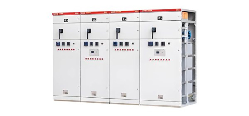
In low voltage systems, the bank is commonly built into an LV panel or distribution board, where the capacitors, switching contactors, fuses, and controller live together behind one enclosure.

This is where power factor correction and low voltage switchgear meet: our LV switchgear assemblies include space and provisions for capacitor steps, and the panel itself carries the protection and metering the bank needs to operate safely.
Housing the bank inside the switchgear keeps installation, maintenance, and future expansion straightforward, because everything is in one place with one set of drawings.
Large industrial plants sometimes correct on the medium voltage side instead, with capacitor banks connected to the MV bus and switched through medium voltage switchgear. MV banks handle larger reactive loads in a single unit and suit facilities with central substations and long feeders.
Whichever side you correct on, the bank also eases the burden on upstream equipment: with less reactive current flowing, transformers run cooler and deliver more of their rated capacity to actual loads, a quiet benefit that shows up in temperature and loading margin.
Conclusion
Effective power factor correction starts with the right system data. Load profile, harmonic levels, switching requirements, and protection settings should all be considered when selecting and integrating a capacitor bank.
Toonice designs and manufactures LV and MV switchgear for industrial and utility applications. Whether you are addressing an existing power factor issue or planning capacitor bank integration for a new distribution system, our engineering team can review your single-line diagram, load data, and utility requirements to help determine a suitable solution.
FAQ
Q How do I know if my facility has a low power factor?
Check your utility bill or electrical metering system. The bill may show power factor, kVA demand, reactive energy, or related charges. For a more accurate assessment, use a power analyzer or switchgear meter to record kW, kVAR, and power factor over a representative operating period.
Q Can a capacitor bank damage motors or other equipment?
A properly designed capacitor bank should not damage connected equipment. Problems can occur if the bank is incorrectly sized or applied in a system with significant harmonics. Proper kVAR sizing, harmonic assessment, suitable switching devices, and coordinated protection help prevent resonance, switching transients, and overcorrection.
Q What does “detuned” mean on a capacitor bank datasheet?
A detuned capacitor bank uses reactors in series with the capacitors to shift the resonant frequency away from dominant system harmonics. Detuned banks are commonly used in networks with VFDs, UPS systems, rectifiers, and other non-linear loads. If harmonic levels are unknown, they should be measured before the capacitor bank is specified.

--- END ---

MV & LV Equipment Manufacturer · Wenzhou, China
COMPANY
PRODUCTS
INDUSTRIES