- Phone / WhatsApp:+86 157 0677 9792
- sales@toonice.com
-
English



MV Switchgear Maintenance: Routine Inspection and Condition Monitoring
Aug 01,2026
Unplanned outages in medium-voltage networks can quickly bring production to a halt. A tripped feeder or switchgear fault may take hours to diagnose and repair, with the resulting downtime often costing far more than the maintenance that could have prevented it.
Regular inspection and condition monitoring help identify developing problems early, allowing maintenance teams to address them during planned outages rather than in an emergency.
At Toonice, we manufacture medium voltage switchgear for utilities, industrial facilities, and renewable energy projects. Our work with both factory testing and field applications has given us a practical understanding of the issues maintenance teams encounter over the life of the equipment.
In this guide, we look at the routine inspections and condition-monitoring practices that help keep MV switchgear safe, reliable, and ready for service.
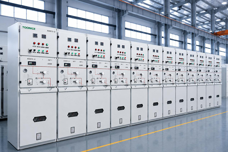
Why MV Switchgear Needs Planned Maintenance
MV switchgear operates under continuous electrical, mechanical, and thermal stress. Switching operations gradually wear operating mechanisms and contacts, load current generates heat at busbar and cable connections, and insulation properties can deteriorate with age, contamination, moisture, and temperature.
Much of this degradation develops gradually and may not be obvious during normal operation. A loose or deteriorating connection, for example, can show only a small increase in resistance at first, but the resulting heat can accelerate further deterioration and eventually lead to failure.
The purpose of MV switchgear maintenance is to identify these developing problems before they affect operation. Inspection, cleaning, mechanical checks, electrical testing, and condition monitoring all play a role, but the required work and maintenance intervals depend on the switchgear design, operating environment, switching frequency, and service conditions.
The manufacturer’s operation and maintenance manual should therefore be the primary reference when planning maintenance, together with the applicable requirements and recommendations of the IEC 62271 series.
A planned inspection may require several hours of scheduled downtime, but dealing with a failure in service can involve fault finding, replacement parts, repair work, and a much longer interruption to the plant or network.
A structured maintenance program gives operators the opportunity to correct wear, loose connections, contamination, and insulation problems at a convenient time rather than after they have developed into equipment failures. It also helps maintain the reliability and service life of the switchgear.
The Routine Inspection Checklist
A practical checklist covers four areas: what you can see, what you can measure with temperature, how the mechanism behaves, and what the electrical tests say. None of these replaces the others, because each one catches a different class of problem.
Visual inspection
Start outside the enclosure. Look for corrosion, paint damage, dents, and signs of impact. Check that doors, hinges, and locks work, and that warning labels remain legible.
Look at cable entries for chafing or pulled glands, and check that the area around the panel is clean and free of stored materials that could block ventilation.
Inside the compartment, look for discoloration, tracking marks on insulation, dust buildup, and any signs of moisture such as condensation or rust. If the unit uses SF6 gas, check the pressure gauge against the marked operating range and record the reading.
Check indicator flags, alarm lamps, and the position indicators for open and closed contacts. Anything that looks unusual should be logged, even if it is not yet a fault.
Infrared thermography
Infrared thermography is one of the most productive checks on the list. With the unit under load, a thermal camera can scan busbars, bolted joints, cable terminations, and fuse holders without touching anything.
A connection that runs hotter than its neighbors is telling you its resistance has risen, often because a bolt loosened after thermal cycling or corrosion crept into the joint.
The key is consistency. Compare each phase against the others, compare readings against the baseline taken when the unit was commissioned, and record the numbers so trends become visible.
A warm spot that stays stable may be acceptable, while a spot that climbs by a few degrees between visits deserves attention. Always follow the equipment manufacturer’s guidance on acceptable temperature rise, and schedule repairs during a planned window instead of waiting for the joint to fail.
Mechanism and contact checks
The operating mechanism is the most mechanically stressed part of any switchgear, and it deserves focused attention. Exercise the breaker or switch through open and close operations, verify the spring charging works, and check that interlocks prevent unsafe sequences.
Lubricate the points specified in the manual, using only the recommended grease, and inspect auxiliary switches and wiring for signs of wear.
Contact condition matters most in switching devices such as vacuum circuit breakers. Contact resistance should be measured with a micro-ohmmeter and compared with the manufacturer’s limit, because rising resistance points to eroded or misaligned contacts.
Vacuum interrupters are sealed, so their internal contact wear cannot be seen directly; electrical checks and operation counts are the practical way to track them. If your plant uses ring main units, the same discipline applies to their load break switches and fuses.

Electrical tests
Electrical testing helps verify the condition of the insulation, protection, and control circuits. Insulation resistance is typically measured with a megohmmeter, with the results compared against previous readings and the equipment manufacturer’s recommendations. Protection relays should also be tested at the recommended intervals.
Secondary injection testing can be used to verify relay operation and trip logic, while functional testing of the trip circuit confirms that the circuit breaker responds correctly to a trip command.
Instrument transformers should be inspected for physical damage, contamination, loose connections, or other signs of deterioration. Where required, CT and VT ratios can also be checked against the equipment ratings and commissioning records.
Where switchgear and power transformers are maintained during the same outage, it is often practical to coordinate the work so both sets of equipment can be inspected and tested within the planned shutdown. Transformer testing should follow the applicable IEC 60076 requirements, manufacturer instructions, and site maintenance procedures.
All readings and test results should be recorded in the maintenance history. Comparing results over time makes it easier to identify gradual changes in insulation resistance, operating performance, or other parameters before they develop into more serious problems.
Condition Monitoring for MV Switchgear
Routine inspections are scheduled, but faults do not keep a schedule. Condition monitoring fills the gap by watching the equipment continuously or at short intervals, so problems are caught between visits.
Partial Discharge Testing and IEC 60270
Partial discharge (PD) is a localized electrical discharge associated with defects such as voids, cracks, or contamination in insulation. It may not cause immediate failure, but continued PD activity can gradually weaken insulation and increase the risk of breakdown.
IEC 60270 defines the conventional electrical method for measuring and evaluating partial discharge. For MV switchgear, online methods such as transient earth voltage (TEV) and ultrasonic detection can identify discharge activity while the equipment remains energized.
Offline testing during a planned outage allows more detailed assessment under controlled conditions.
Interpreting PD Results
A single PD reading provides limited information, so results should be compared over time. An increase in discharge magnitude or a change in pattern or location may indicate developing insulation problems.
The same approach applies to temperature, contact resistance, and breaker operating times. Establishing baseline values at commissioning and tracking changes over time helps maintenance teams identify deterioration and plan corrective work before reliability is affected.
Suggested Maintenance Intervals
| Interval | Typical Tasks | Notes |
| Monthly | Visual walkaround, indicator and alarm checks, enclosure and ventilation check, ambient temperature and humidity check | Quick, can be done by site staff; log everything |
| Quarterly | Detailed visual inspection, infrared thermography under load, SF6 pressure check where applicable, cleanliness review | Most items can be done with the unit energized |
| Yearly | Mechanism operation checks, contact resistance and insulation resistance tests, relay and trip circuit tests, torque checks on connections | Coordinate with a planned outage |
| Major overhaul | Full internal inspection, contact replacement if wear limits are reached, mechanism overhaul, high voltage tests | Intervals vary by manufacturer and duty; follow the OEM manual |
Common Failure Modes We See
In our work with customers around the world, the same few failure modes show up again and again:
- Loose connections: Bolted joints loosen under thermal cycling and vibration. The resistance rises, the joint heats, and the heat accelerates the loosening. Infrared thermography and periodic torque checks catch this early.
- Degraded insulation: Dust, moisture, and aging lower the withstand strength of insulation. Tracking marks and PD activity are the early signs, which is why PD testing per IEC 60270 earns its keep.
- Mechanism wear: Springs weaken, latches bind, and linkages lose adjustment after thousands of operations. The result is a breaker that operates slowly or fails to close on command. Operation counts and regular exercising keep this visible.
- Moisture ingress: Condensation inside the enclosure, often from poor sealing or ventilation, corrodes contacts and contaminates insulation. Heater checks and sealing inspections are simple and effective defenses.
Conclusion
Effective MV switchgear maintenance comes down to regular inspection, testing, and consistent record keeping. Visual checks, thermographic surveys, mechanical inspections, electrical tests, and condition monitoring can help identify deterioration early and reduce the risk of unplanned outages.
Toonice manufactures MV switchgear, vacuum circuit breakers, and ring main units for utility, industrial, and renewable energy applications. If you need support with equipment selection, testing, or maintenance planning, contact our team to discuss your project and operating requirements.
FAQ
Q How often should MV switchgear be maintained?
Maintenance intervals depend on the equipment, operating conditions, and environment. Follow the manufacturer’s recommended schedule, with more frequent inspections for switchgear in dusty, humid, or high-duty applications.
Q Can condition monitoring replace routine maintenance?
No. Condition monitoring helps detect developing problems, but routine inspection and testing are still needed to identify mechanical wear, contamination, loose connections, and control issues.
Q What is partial discharge testing in MV switchgear?
Partial discharge (PD) testing detects electrical discharge associated with insulation defects. Online methods can screen energized switchgear, while offline testing provides a more detailed assessment during planned outages.

--- END ---

MV & LV Equipment Manufacturer · Wenzhou, China
COMPANY
PRODUCTS
INDUSTRIES