- Phone / WhatsApp:+86 157 0677 9792
- sales@toonice.com
-
English


Inside a Compact Substation: How to Read the Specification Table
Sep 22,2026
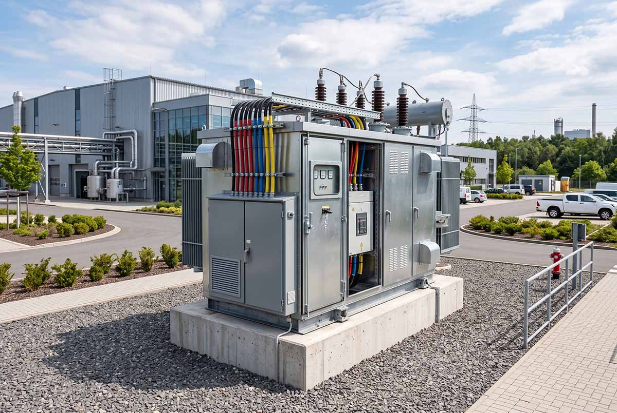
A compact substation combines the high-voltage switch, the transformer, and the low-voltage distribution into one enclosure. The unit is assembled and tested as a package, placed on a foundation, and connected to the network, which removes most of the site work that a conventional substation room requires.
That packaging is why the specification table matters more than the product description. The table carries the parameters that decide whether the unit suits a project: voltage class, capacity range, impedance, losses, temperature rise, noise, and the type of high-voltage switch inside.
This article works through those parameters for the America type substation range, in which high-voltage switchgear, plug-in transformers up to 36 kV on the high-voltage side, and low-voltage distribution are integrated into a single fully sealed unit.
The Voltage Classes and What They Change
The range covers three voltage combinations: 10 kV/0.4 kV, 10 kV/0.69 kV, and 35 kV/0.4 kV. The two 10 kV configurations cover many conventional distribution and industrial applications, while the 35 kV version is intended for systems with a higher incoming voltage.
These configurations differ in more than transformer ratio. Voltage class also affects insulation requirements, short-circuit impedance, available capacity, and the type of high-voltage switching equipment used in the enclosure. Those differences need to be considered as part of the overall substation design.
Published capacities range from 30 to 1600 kVA for the 10 kV/0.4 kV version and from 50 to 1250 kVA for 10 kV/0.69 kV. The 35 kV/0.4 kV configuration extends from 100 to 2500 kVA, reflecting the larger loads typically associated with that voltage class.
The standard frequency is 50 Hz, with 60 Hz available where required. Frequency should be confirmed at the design stage along with the system voltage and connected equipment, since it affects equipment selection rather than being a field adjustment made after manufacture.
Insulation Level and Short-Circuit Impedance
The high-voltage insulation level is specified by the power-frequency withstand voltage. For the 10 kV configurations, the published value is 42 kV for 1 minute, while the 35 kV version is rated at 95 kV for 1 minute. This rating reflects the insulation level required by the voltage class rather than the transformer capacity.
Short-circuit impedance also changes with the system configuration. The 10 kV versions are available with 4% or 4.5% impedance, while the 35 kV version uses 6% or 8%.
The impedance value affects how the transformer behaves during both normal operation and fault conditions. Increasing impedance helps limit fault current on the low-voltage side, but it also increases voltage drop under load. The appropriate value therefore needs to be coordinated with the expected load, available fault level, and protection settings rather than selected in isolation.

Capacity, Losses, and the Cost of Standing Load
Transformer losses matter because they affect operating cost in different ways. No-load loss is present whenever the transformer is energized, even when it is supplying little or no load. Load loss increases as current rises and becomes more significant as the transformer approaches its rated capacity.
Across the published range, no-load current is 0.6% to 1.8%, with no-load losses from 0.24 to 4.0 kW. Load losses range from 1.25 to 25.0 kW depending on transformer capacity. Loss performance is specified in accordance with GB/T 17467.
These figures are especially relevant when selecting transformer capacity. An oversized unit may spend much of its operating life lightly loaded while still carrying its no-load loss continuously. For installations with large variations in demand, the expected load profile should therefore be considered alongside the nameplate capacity and efficiency figures.
A transformer sized reasonably close to the actual operating load will often provide a better balance between available capacity, losses, and long-term energy cost than simply choosing the largest rating available.
Vector Group and Connection
The published vector group options are Y,yn0 and D,yn11. The choice affects phase relationship, neutral availability, and how the transformer behaves under unbalanced and zero-sequence conditions, so it should be matched to the distribution system rather than treated as a standard default.
Tap adjustment is specified at ±5%, with options in ±2 × 2.5% steps. This gives the transformer some ability to compensate for variation in the incoming supply and keep the secondary voltage within the required operating range.
The winding temperature rise is rated at 65 K across the range. Published noise levels are 65 dB or below for the 10 kV configurations and 70 dB or below for the 35 kV version. Those limits become more important where the substation is installed close to occupied buildings or other noise-sensitive areas.
The High-Voltage Switch and the Protection Chain
The high-voltage switch inside the enclosure is published as a three-position load break switch with fuse on the two 10 kV arrangements, and as an SF6 load break switch with fuse on the 35 kV arrangement.
The operating mechanism is a spring energy storage mechanism across the range, with a motorized mechanism available on the 35 kV arrangement. The fuse handles short-circuit interruption while the load break switch handles normal switching, which is why the pair is specified together.
Insulation follows the same pattern. The 10 kV arrangements use oil-immersed fully sealed insulation, while the 35 kV arrangement uses oil-immersed insulation with SF6 auxiliary insulation. The sealed design keeps moisture, dust, and contaminants out, and the insulating oil serves both insulation and heat dissipation.

Sealed Construction and Maintenance Expectations
A compact substation is typically installed outdoors, so the transformer and enclosure need to be designed for long-term exposure to the local environment. A sealed oil-immersed transformer reduces routine maintenance requirements and helps protect the insulation system from moisture and external contamination.
The published range references IEEE, IEC, and GB/T standards, with loss performance specified in accordance with GB/T 17467. Any project-specific standard or utility requirement should be confirmed during the design stage so that it can be reflected in the equipment selection, drawings, and test documentation.
The published ratings also need to be considered together. Capacity affects thermal performance, while temperature rise and noise can influence how and where the substation can be installed. Increasing transformer capacity within a compact enclosure may require corresponding changes to cooling and ventilation.
Local conditions are part of the same engineering review. Ambient temperature, altitude, ventilation around the enclosure, and installation arrangement can all affect thermal performance. Defining these conditions before manufacture allows the substation to be designed around the environment it will actually operate in.
Conclusion
Compact substation selection works best when the main electrical parameters are considered together rather than one at a time. Voltage class influences the available capacity, insulation level, impedance, and high-voltage equipment, while transformer capacity affects losses, thermal performance, and noise.
Impedance and vector group deserve particular attention because both have a direct effect on how the substation behaves in the system. Impedance needs to be coordinated with the available fault level and protection settings, while the vector group should suit the distribution arrangement and the loads being supplied.
Once those fundamentals are defined, the rest of the specification becomes much easier to finalize. Since the unit is assembled and tested before delivery, the quality of the site installation depends heavily on how clearly the electrical and environmental requirements were established at the design stage.
Ready to finalize the specifications for your next compact substation project? Contact our engineering team for detailed technical support and tailored solutions.

--- END ---

MV & LV Equipment Manufacturer · Wenzhou, China
COMPANY
PRODUCTS
INDUSTRIES