- Phone / WhatsApp:+86 157 0677 9792
- sales@toonice.com
-
English



Metal-Clad Withdrawable Switchgear for 12 kV to 40.5 kV Systems
Sep 30,2026
Medium-voltage distribution in an indoor substation is usually built around metal-clad withdrawable switchgear. The circuit breaker sits in its own compartment, the busbars and cables are separated from it, and the breaker can be withdrawn for maintenance without opening the enclosure.
The range is organized by voltage class. The differences between a 12 kV panel and a 40.5 kV panel are not limited to size: insulation distances, withstand values, current ratings, and fault ratings all change with the class, and the panel dimensions follow.
This article compares the published values across the classes, explains how to read the insulation figures, and lists the inputs that have to be settled before a panel is built.
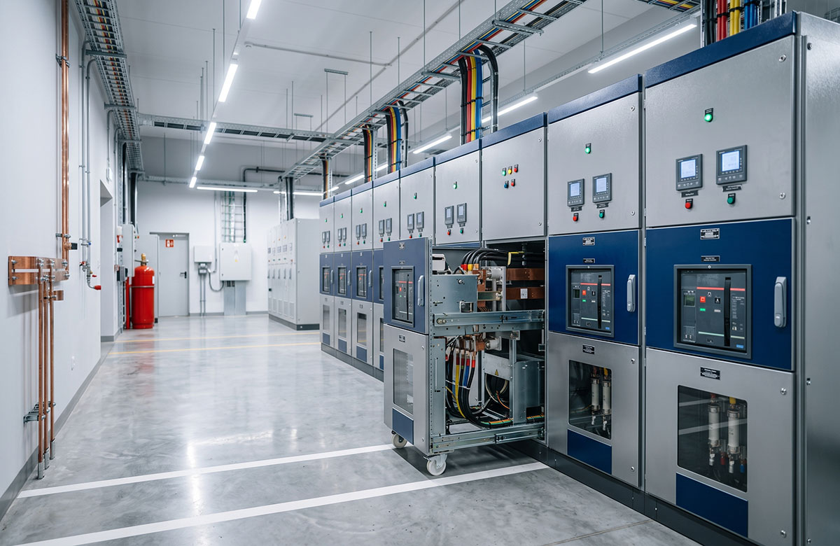
Metal-Clad and Withdrawable Construction
Metal-clad switchgear separates the primary circuits into individual compartments using grounded metal barriers. In a withdrawable design, the circuit breaker is mounted on a truck or carriage that can be moved between service, test, and isolated positions.
This arrangement is useful where maintenance access and circuit availability are important. A feeder can be isolated without taking the entire busbar out of service, and a breaker can be removed for inspection or replacement without dismantling the fixed parts of the panel.
The switchgear ranges covered here use withdrawable vacuum circuit breakers. Main busbars are typically copper, while protection, control, and interlocking functions are configured to suit the project. These details determine how the switchgear is operated, maintained, and integrated with the rest of the electrical system.
Voltage Classes and System Ratings
The KYN28 range is published in three rated voltage classes: 12 kV, 17.5 kV, and 24 kV. The typical system voltages behind those classes are 10 or 11 kV, 13.8 or 15 kV, and 20 or 22 kV respectively.
The KYN61 range is published in a single class at 40.5 kV, with a typical system voltage of 35 kV. The gap between the rated voltage of the equipment and the nominal voltage of the system is intentional: the panel has to withstand the highest voltage the network can produce, not the nominal value.
Frequency is published at 50 or 60 Hz across both ranges, which allows the same construction to be applied to projects in different regions without redesign.
How to Read the Insulation Withstand Values
Each voltage class has separate insulation withstand requirements for the main circuit and for the isolating distance. The phase-to-earth and phase-to-phase rating applies to the normal insulation system, while the isolating-distance rating applies across the open gap created when the breaker or disconnector is moved to the isolated position.
For the KYN28 range, the published power-frequency withstand values are 28/32 kV for the 12 kV class, 38/45 kV for 17.5 kV, and 50/60 kV for 24 kV. The corresponding lightning impulse withstand values are 75/85 kV, 95/110 kV, and 125/145 kV.
The KYN61 range, designed for the 40.5 kV class, is rated at 95 kV power-frequency withstand and 185 kV lightning impulse withstand. The higher insulation requirement is one reason 40.5 kV switchgear needs greater internal clearances and a larger enclosure than lower-voltage designs.
When comparing these ratings, the value across the isolating distance should not be overlooked. It represents the dielectric strength required across the open isolation gap and is part of the switchgear’s insulation coordination when the withdrawable device is in the disconnected position.

Current and Fault Ratings
Continuous current and short-time withstand current describe different limits of the switchgear. The rated current is the load the panel can carry in normal service, while the short-time withstand rating defines the fault current the main circuit can tolerate for the specified duration.
For the KYN28 range, the published rated current reaches 4000 A, with short-time withstand current up to 40 kA. The KYN61 range is rated up to 2500 A, with short-time withstand current up to 31.5 kA.
The lower current figures on the higher-voltage KYN61 range do not indicate lower overall system capability. They reflect the way current requirements change with system voltage and the intended application of the equipment. The correct rating still needs to be checked against the expected load current and the available fault level at the point of installation.
Applications by Voltage Class
Both ranges are designed for indoor primary power distribution in utility, industrial, and infrastructure power systems, and the choice between the classes follows the system voltage rather than the load alone.
A 12 kV panel suits a 10 or 11 kV network, which is the common distribution level in industrial plants and commercial installations. The 17.5 kV and 24 kV classes serve 13.8, 15, 20, and 22 kV systems, which appear in different regional standards. The 40.5 kV class serves 35 kV systems, where the substation usually feeds a larger area.
Getting the class right is what keeps the rest of the specification stable. Voltage class, insulation level, current rating, and enclosure dimensions follow from one another, so a change in class late in the project affects the room layout as well as the equipment.
Compartments, Protection, and Internal Arc
The enclosure is rated IP4X, while the internal compartments are rated IP2X. In practical terms, IP4X helps prevent small solid objects from entering the cabinet, and IP2X provides basic protection against accidental finger contact with live parts inside the compartments.
Internal arc classification depends on the project. Where a specific internal arc rating is required, it needs to be coordinated with the compartment layout, pressure-relief arrangement, and the way the switchgear is installed in the room.
Protection, control, and interlocking functions are also configured around the application. The final arrangement is normally defined by the system voltage, switchgear configuration, installation environment, and the operating requirements of the project.
Installation, Cable Entry, and Project Inputs
Bottom cable entry is the standard arrangement, although other options can be used where the site layout requires them. The entry position needs to be coordinated with the cable trench, available space below the panel, cable routing, and the surrounding civil works.
Before the switchgear is engineered, the main system requirements need to be clear. These usually include system voltage, rated current, short-circuit level, the single-line diagram, and the project specification. From there, the appropriate voltage class, insulation level, current rating, and protection arrangement can be defined.
Conclusion
Metal-clad withdrawable switchgear should be selected around the electrical system it will serve. System voltage determines the voltage class and insulation requirements, while continuous current and short-time withstand ratings need to match the expected load and available fault level.
Insulation withstand values also deserve careful attention, especially the rating across the isolating distance. It serves a different purpose from the main phase-to-earth and phase-to-phase insulation rating and should be read accordingly when comparing switchgear classes.
Once the main electrical ratings and cable-entry arrangement are defined, protection, control, and interlocking can be developed around the operating requirements of the project. Resolving those details during the design stage helps ensure the finished switchgear arrives with the right configuration for the installation.
Ready to finalize the technical specifications for your medium-voltage distribution project? Contact our engineering team for tailored solutions and expert support.

--- END ---
Already the last article
Next: Inside a Compact Substation: How to Read the Specification Table

MV & LV Equipment Manufacturer · Wenzhou, China
COMPANY
PRODUCTS
INDUSTRIES