- Phone / WhatsApp:+86 157 0677 9792
- sales@toonice.com
-
English
How Power Transformers Increase Voltage
Jul 01,2026
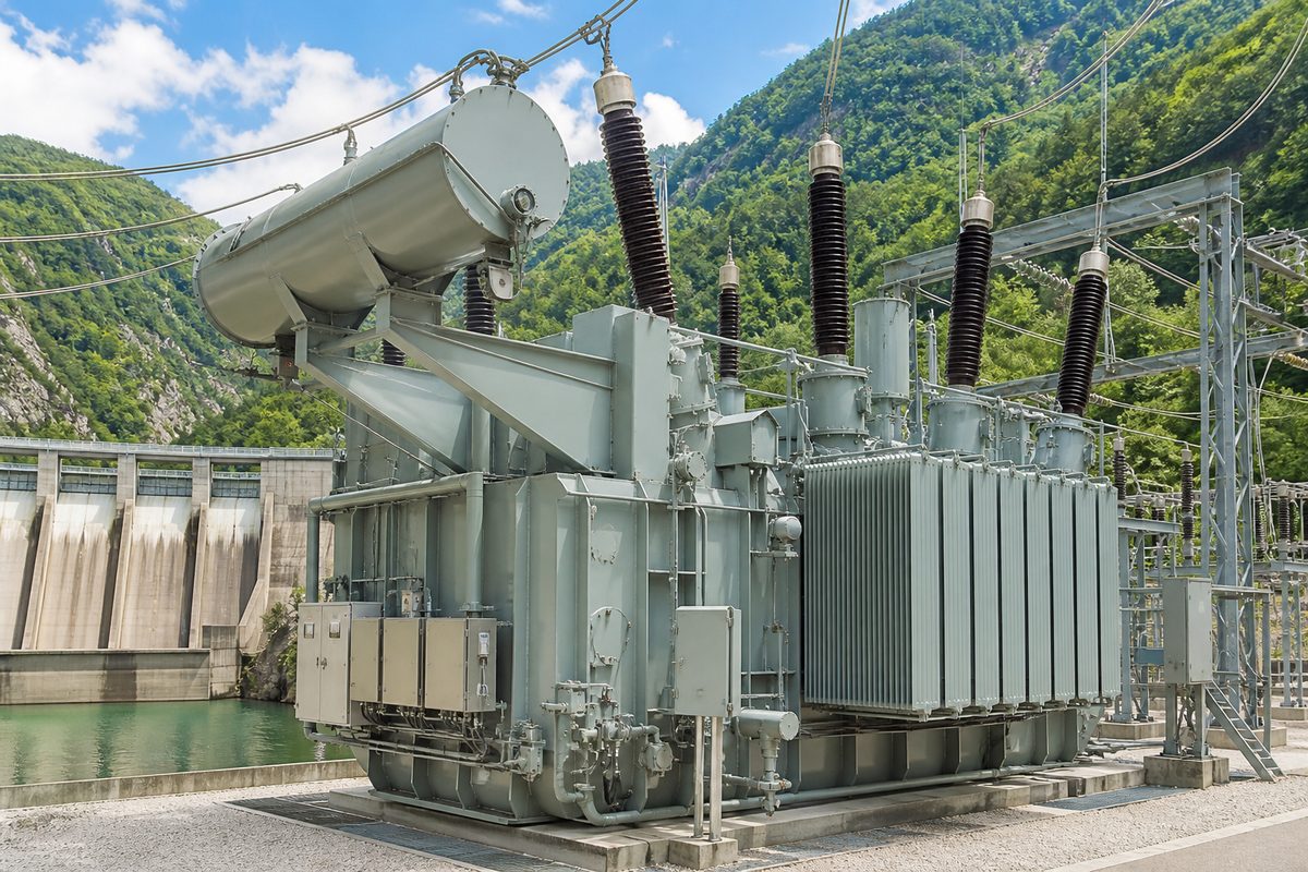
Power transformers stand as fundamental components within modern electrical grids, designed to alter alternating current voltage levels. Raising voltage efficiently helps reduce energy loss across long transmission lines while delivering steady electricity to end users. A transformer consists of a silicon steel iron core, copper or aluminum windings, and insulating materials.
This article explains the primary function, working principles, voltage elevation mechanisms, and application settings of power transformers.
Key Takeaways
Primary Function of Power Transformers
A power transformer operates on electromagnetic induction as a static device, modifying alternating current voltage and current without changing system frequency. Power transformers act as energy conversion nodes within electrical networks. Electricity generated at power plants undergoes initial voltage elevation through transformers for long-distance transport across high-voltage transmission lines, after which step-down transformers lower the supply to safe levels for industrial, commercial, and residential consumption.
How Power Transformers Increase Voltage
Electromagnetic Induction Principles
Voltage elevation in power transformers relies on Faraday’s law of induction. Alternating current flowing through the primary winding creates a time-varying magnetic field, which the high-permeability iron core gathers and routes toward the secondary winding. As the alternating magnetic flux passes through the secondary coil, an electromotive force develops at the matching frequency, transferring energy from the primary side to the secondary side while altering voltage levels.
Turns Ratio and Voltage Elevation
The voltage output on the secondary side depends on the ratio of coil turns between the primary and secondary windings. Step-up transformers feature significantly more secondary coil turns than primary turns. Voltage scales directly with the turn count, which means coils with more turns experience higher induced voltages under identical magnetic flux conditions. Specific winding designs allow transformers to raise low input voltages to target output levels.
Energy Conservation and Current Adjustment
Step-up operations follow energy conservation principles, which dictate that ideal input power equals output power when ignoring minor core and conductor losses. Elevating secondary output voltage causes a proportional drop in output current. Operating at higher voltages and lower currents decreases heat generation along conductors, which lowers requirements for wire current capacity and cross-sectional area.
Operational Principles of Step-Up Transformers
Step-up transformers convert electrical energy into magnetic energy and back into electrical energy.
When an alternating voltage V₁ enters the primary coil, an alternating current I₁ flows and generates a varying magnetic flux Φ within the core. This flux crosses the secondary coil with turn count N₂, inducing output voltage V₂ according to the following relationship:
Step-up transformers maintain higher secondary turn counts than primary turn counts (N₂ > N₁), producing an output voltage greater than the input voltage (V₂ > V₁). Based on power balance (V₁I₁ = V₂I₂), output current I₂ decreases accordingly.
Why Voltage Elevation Matters in Power Systems
Voltage elevation maintains a central position in large power networks. Conductors present fixed resistance, which makes line heat losses proportional to the square of the current (Ploss ∝ I²R). Increasing transmission voltage significantly reduces line current for a given power level, cutting energy losses during transport and improving long-distance transmission economics and stability.
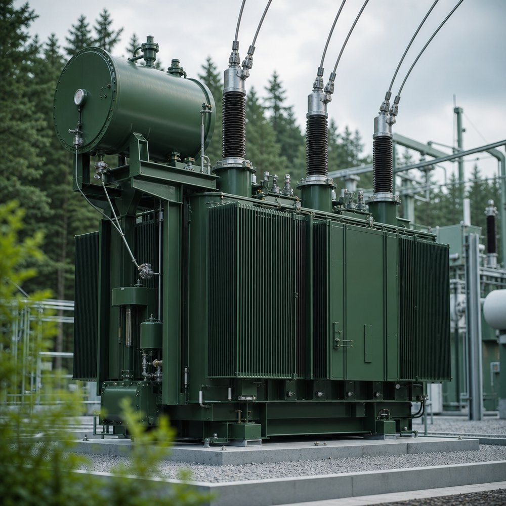
Settings Where Step-Up Transformers Operate
Power Plant Generation Outlets
Large power stations like hydroelectric, thermal, and nuclear facilities generate electricity at moderate voltage levels that cannot support transmission over hundreds of kilometers. Generation outlets require large-capacity step-up transformers to raise voltage to 220 kV, 500 kV, or higher ultra-high-voltage levels, which allows bulk power to enter main transmission grids smoothly.
Renewable Energy Station Collection Lines
Wind farms and solar plants feature distributed installations with modest individual unit outputs, generating power at several hundred to several thousand volts. Facilities run power through step-up transformers, often housed in box-type substations, to elevate low voltages step by step up to 35 kV or 110 kV before grid connection, which reduces internal collection line power losses while meeting grid connection standards.
Regional Ultra-High-Voltage Transmission Projects
Step-up transformers serve as core hardware at sending stations in long-distance, high-capacity interregional grid interconnections. Alternating current ultra-high-voltage projects and direct current transmission converters rely on step-up transformers to build high-voltage corridors, enabling wide-area power distribution and efficient grid dispatching.
| Aspect | Step-Up Path | Step-Down Path |
|---|---|---|
| Typical role | Raise plant or collection voltage for transmission | Lower supply to safe industrial and residential levels |
| Turns relationship | N₂ > N₁ → V₂ > V₁ | N₂ < N₁ → V₂ < V₁ |
| Current effect | Output current decreases as voltage rises | Output current increases as voltage falls |
| System benefit | Cuts I²R losses on long lines | Matches end-user safety and equipment ratings |
Conclusion
Power transformers elevate alternating current voltage through electromagnetic induction and specific coil turn ratios. Step-up technology solves power loss challenges in long-distance transmission, supporting low-cost energy transport across modern electrical networks. Understanding transformer mechanisms provides insight into grid operation and power distribution.
Need the Right Transformer?
Toonice offers a wide range of transformer models and types, including oil-immersed and dry-type designs. You are welcome to visit our homepage to browse and select the products you need, or contact our team.
FAQs
No. Transformers require changing magnetic fields to induce voltage, whereas direct current produces a steady magnetic field that cannot trigger induction.
No. Transformers modify voltage and current levels without generating additional energy, leaving output power equal to input power minus minor operational losses.
Induced voltage correlates directly with coil turn counts, meaning additional secondary turns generate higher total output voltages.
High-voltage transport minimizes line loss over distance, while low-voltage delivery ensures safety and equipment compatibility for end users.
Both types share identical operational mechanics and differ primarily in winding configurations, where step-up units use finer wire with more turns on the secondary side and step-down units use thicker wire with fewer turns on the secondary side.

--- END ---

MV & LV Equipment Manufacturer · Wenzhou, China
COMPANY
PRODUCTS
INDUSTRIES