- Phone / WhatsApp:+86 157 0677 9792
- sales@toonice.com
-
English

Vacuum Circuit Breaker Racking Procedure: A Step-by-Step Safety Guide
Oct 02,2026
Racking a vacuum circuit breaker (VCB) truck is a routine but safety-critical operation in medium-voltage switchgear. Moving the breaker between the disconnected, test, and service positions requires a clear understanding of the racking mechanism, electrical and mechanical interlocks, and proper operating procedures. Incorrect operation can lead to equipment damage, arc flash hazards, or serious injury.
Before operating the racking handle, it is essential to verify the breaker status, confirm the required interlock conditions, and understand the function of each truck position. Following the manufacturer’s instructions and established safety procedures helps ensure smooth, controlled, and reliable VCB truck operation.
What a Truck Is and What It Is Not
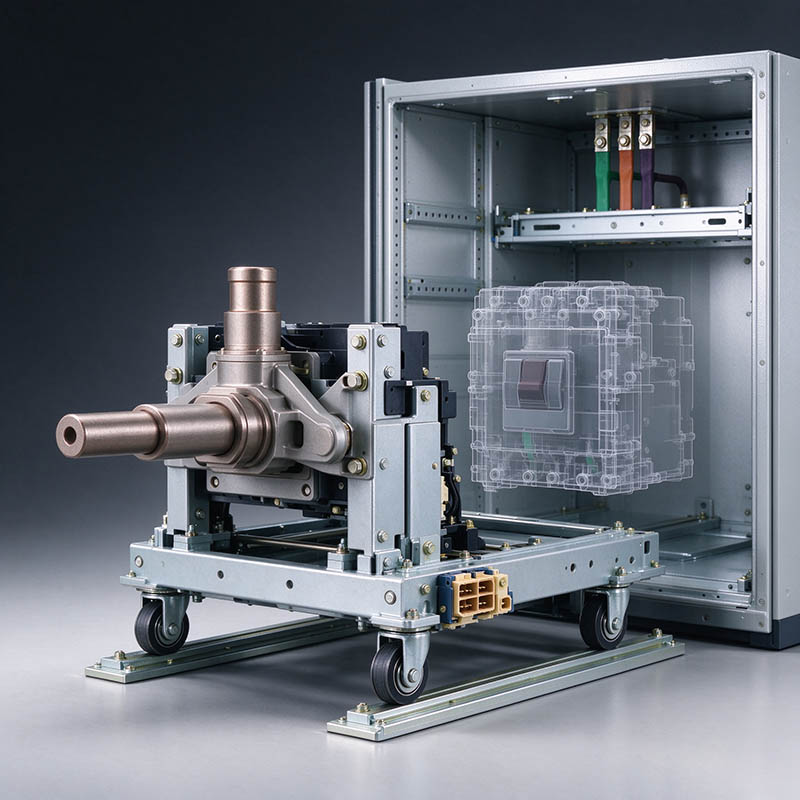
A withdrawable truck carries the primary contacts of a switching device and moves them between the busbar and the cable compartment. An isolation truck does exactly that—connection and isolation, and nothing more. It is not intended for load switching, and it is not intended to interrupt a short circuit.
That distinction matters because a truck that looks like a breaker is not a breaker. The device mounted on it does the switching. The truck only moves the device into a position where it can do that switching safely.
Trucks are built for 12 kV, 17.5 kV, 24 kV, and 40.5 kV systems, with dimensions, primary contacts, rated current, and interlocking interfaces configured to the switchgear they belong to. The same truck model will not fit two different board designs, which is why the switchgear drawing always travels with the order.
The Positions a Truck Moves Through
Every racking operation is a movement between defined positions, and each one has a rule attached.
| Position | Primary Contacts | What It Means | What Is Permitted |
|---|---|---|---|
| Connected | Engaged with busbar and cable | Device in service | Normal switching |
| Test | Separated, auxiliary still engaged | Control and interlocks can be tested | Test operations only |
| Withdrawn | Fully out on the rails | Device removed from the circuit | Inspection and removal |
The test position is the one that gets misused. It exists so the control circuit, the trip coil, and the interlocks can be proven without energizing the primary circuit. Treating it as a safe working position while the auxiliary contacts stay engaged is how control voltage finds its way into places an engineer did not expect.
Our guide to vacuum circuit breaker types covers the devices that ride on these trucks, and the truck itself is only the carriage.
Interlocks That Must Be Proven
Interlocks are mechanical logic, and mechanical logic fails quietly. Three of them deserve a test at every maintenance interval.
Breaker Status Lock
The first prevents racking while the breaker is closed.
Position Engagement Lock
The second prevents closing the breaker unless the truck sits fully in the connected or test position.
Earthing Switch Logic Lock
The third prevents the truck from being moved while the earth switch is closed, and prevents the earth switch from closing while the truck is connected.
Proving them means moving the truck through its positions with the primary isolated and watching what the mechanism refuses to do. An interlock that allows a forbidden movement has already failed, even if nobody has been hurt yet.
Where the board uses a metal-clad construction, the shutters and the compartment barriers add a second layer behind the interlock. Our comparison of metal clad and metal enclosed switchgear explains how far that separation goes in each design.
Racking In and Out Step by Step
The sequence below is the order that keeps people out of the fault path. Follow the switching program for the specific board, and treat this as the mechanical logic behind it.
Confirm the switching authority and the permit for the section before touching the handle.
Check which position the truck occupies on the indicator, and confirm it against the panel schedule rather than against memory.
Open the device on the truck and confirm the position indicator shows open, not just the control lamp.
Rack from connected to test with the handle, watching the shutter action, and stop if resistance appears before the test position.
Perform the required test operations at the test position, then move to withdrawn for inspection or removal.
When racking in, stop at test, close the compartment door, and confirm the auxiliary contacts engage before continuing to connected.
Record the final position and the time in the switching log, and restore the interlocks to their normal state.
Resistance on the handle is information. A truck that will not rack smoothly has a misalignment, a damaged contact, or a jammed shutter, and forcing it damages all three.
Inspection Points Before Every Rack
Most racking problems are visible before the handle turns. Inspect the truck and the compartment when the unit is withdrawn, and you remove the surprises.
| Check | What to Look For | Consequence If Ignored |
|---|---|---|
| Primary contacts | Discoloration, pitting, transfer marks | Overheating at the joint under load |
| Shutter operation | Free movement, correct closing on rack out | Contacts exposed and live |
| Racking mechanism | Smooth travel, no binding or noise | Forced racking damages contacts |
| Auxiliary contacts | Bent pins, wear on the block | Control and interlock failures |
| Wheels and rails | Flat spots, debris in the floor channel | Misalignment on racking |
| Heater circuit | Warm to the touch, no condensation | Flashover risk on humid days |
A medium voltage switchgear maintenance guide sets the interval for these checks, and the racking handle is only the last step in a routine that starts with the compartment door.
Different Types of Trucks in Medium-Voltage Switchgear
Not every truck carries a breaker. A metering truck carries voltage and current transformers so the metering circuit can be tested and maintained without switching the primary. A voltage transformer truck does the same duty where the transformers need their own carriage.
Those units are configured to the switchgear design in the same way, and the position rules apply to them equally. The danger is different, though, since a truck carrying instrument transformers has no breaking capability at all and depends entirely on being racked into the right position.

Frequently Asked Questions
Can an isolation truck switch load current?
No. It performs connection and isolation only, and it is not intended for load switching or short-circuit interruption. The switching device on the truck handles current.
What is the test position for?
It separates the primary contacts while keeping the auxiliary circuits engaged, so controls, trip circuits, and interlocks can be tested without energizing the primary circuit.
How often should interlocks be tested?
At every scheduled maintenance interval, and after any work that disturbs the compartment, the shutter, or the racking mechanism. A mechanical interlock has no self-test function.
Can I rack a truck with the breaker closed?
No. The interlock should prevent it, and any attempt that succeeds is a defect to report rather than a shortcut to use.
What information do you need for a truck enquiry?
Send the switchgear type and drawing, the rated voltage and current, the contact arrangement, and the interlocking interface. Trucks are built to the board, so the drawing is the starting point.
Safe VCB Racking Starts with the Right Procedure
Safe vacuum circuit breaker (VCB) truck racking involves more than simply turning a handle. It requires a clear understanding of truck positions, proper verification of breaker status, functional interlocks, and strict adherence to the switchgear manufacturer’s operating procedures. Every step matters in preventing equipment damage, operational errors, and potential electrical hazards.
Choosing the right switchgear truck is equally important for reliable operation. At Toonice, we offer isolation trucks for 12 kV to 40.5 kV switchgear applications, as well as metering trucks designed for instrument transformer applications. Our products are engineered to meet specific switchgear requirements, including contact configurations, mechanical interfaces, and interlocking arrangements, with reference to IEC 62271-200.

--- END ---

MV & LV Equipment Manufacturer · Wenzhou, China
COMPANY
PRODUCTS
INDUSTRIES