- Phone / WhatsApp:+86 157 0677 9792
- sales@toonice.com
-
English

How to Specify an Automatic Transfer Switch Cabinet
Oct 05,2026
When utility power fails, a standby generator may take around ten seconds to start and become ready to supply power. During this interval, the automatic transfer switch (ATS) monitors the power sources and manages the transfer according to its configured settings. How the system responds depends on several decisions made during the design and equipment selection stages.
At Toonice, we manufacture automatic transfer switch (ATS) cabinets for a range of power distribution applications. In our experience, many installation and commissioning issues come down to three factors that should be clarified before ordering: the transfer sequence, the electrical requirements, and the control configuration.
Understanding the Role of an ATS in a Power Distribution System
The same transfer switch belongs in very different cabinets depending on where it goes. At the service entrance, it carries the whole building load, so it becomes service equipment with utility approval implications. Downstream of a main board, it may only carry a critical sub-panel, and the cabinet shrinks with the load.
Decide that position first, because it fixes the current rating, the fault level at the terminals, and the form of separation. A switch sized for a sub-panel will not survive a later move to the service entrance.
Choose the Switching Device Inside the Cabinet
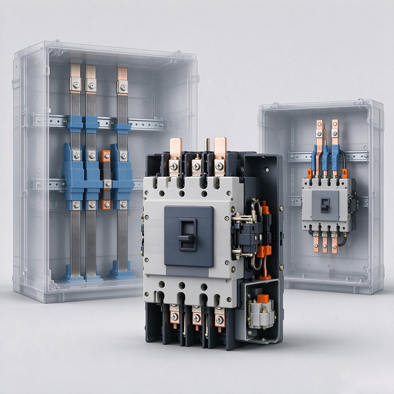
Inside the enclosure, the transfer happens through one of three devices, and the choice drives cost, breaking capacity, and maintenance.
| Device | Typical Use | Strength | Watch Out For |
|---|---|---|---|
| Contactor pair | Loads up to a few hundred amps | Fast transfer, low cost | Needs upstream protection, limited withstand |
| MCCB pair | Most commercial and industrial panels | Adjustable protection built in | Slower transfer, larger enclosure |
| ACB pair | High current main transfer | High withstand, serviceable | Cost, footprint, lifting weight |
A contactor-based cabinet transfers quickly and suits motor and lighting loads where a short interruption is acceptable. An MCCB-based cabinet brings overcurrent protection into the same device, which simplifies coordination. An ACB pair suits a whole service at high current where the owner expects to service devices in place.
Ask for the device make and model in the quotation rather than the current rating alone, because two cabinets at the same rating can differ by a factor of several on short-circuit withstand.
Poles, Neutral and Grounding
Three-pole transfer switches switch the phases and leave the neutral solid. Four-pole switches break the neutral as well. The choice is not a preference; it follows from the grounding design.
A four-pole ATS is needed where the generator is a separately derived source with its own neutral-to-ground bond. Without a switched neutral, the two bonds run in parallel, current circulates through the ground path, and residual current devices trip.
Where the neutral stays solid, confirm a single bonding point and that the neutral is treated as a conductor throughout. Getting this wrong is the most common reason an ATS cabinet trips an RCD on transfer, and no datasheet reveals it.
| Configuration | Neutral | Use It When | Reference Notes |
|---|---|---|---|
| Three-pole | Solid, not switched | Single bonding point, neutral grounded once | Standard single-ground installations |
| Four-pole | Switched with the phases | Generator bonded separately, or two sources overlap | Our guide to distribution board types and functions covers how the neutral bar is handled in panels on either side of the transfer. |
Sizing and Protection Coordination
Rated current is a starting point, not the answer. Size for the continuous load, then check the motor contribution and the inrush from loads that restart after transfer. A cabinet rated exactly at the calculated load can trip when a large motor group restarts on the generator.
Protection coordination has two levels. The transfer devices must withstand the prospective fault current for as long as the upstream device needs to clear it, and the upstream breaker must be chosen so the pair has been tested together. A type-tested assembly to IEC 61439-2 is the document that proves it.
Where the transfer feeds a panel with power factor correction, check the sequence as well. Our article on power factor correction capacitor banks explains why the bank should be switched out before the transfer and restored once the load is stable.
Controller Functions Worth Paying For
The controller decides when to transfer and when to come back, and basic voltage monitoring on both sources is the minimum. Add adjustable voltage and frequency windows, a generator start signal with a cool-down timer, a test mode that exercises the transfer without dropping the load, and an event log that stamps every transfer.
The event log matters more than it looks. When a transfer fails at two in the morning, the log shows whether the controller saw a valid source and refused to switch, or never saw one at all.
Set the transfer and retransfer delays during commissioning rather than accepting factory values. A retransfer delay shorter than the cool-down shortens equipment life, and a transfer delay that is too short switches onto a source that has not settled.
Standards, Documents and Commissioning
Ask for the assembly standard and the transfer equipment standard separately. The cabinet is an assembly to IEC 61439-1 and IEC 61439-2, while the equipment inside follows IEC 60947-6-1 where that standard applies. A supplier who quotes only one has not separated the two halves of the job.
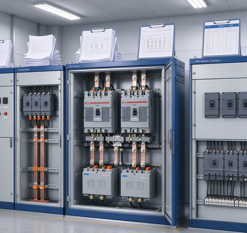
Documentation should include the single-line diagram, the terminal layout, the device datasheets, and the factory routine test record. Those four are what an inspector asks for, and chasing them after shipment costs weeks.
Commissioning follows a fixed sequence. Simulate a utility loss and confirm the transfer time, then check that the generator start command reached the set. Simulate the return of utility and verify the retransfer with its cool-down, run a load test at the actual current, and record every transfer time against the specification before handover.
The cabinet should also match the equipment beside it. Our overview of low voltage switchgear cabinet types shows how transfer cabinets sit alongside feeder cabinets in one room, and an XL-21 distribution cabinet is often the downstream partner.
Frequently Asked Questions
What is the difference between an ATS and a manual transfer switch?
An ATS transfers automatically when it detects loss of the normal source. A manual switch needs an operator to move the handle, so it suits sites where someone is always present.
How long does an ATS take to transfer?
It depends on the controller settings and the switching device. Contactor-based cabinets move in a fraction of a second, breaker-based cabinets take longer, and the specification should state the number.
Do I need a 3 pole or 4 pole ATS?
Use four poles when the standby source has its own neutral-to-ground bond, which is common with generators. Three poles suit installations with a single bonding point and a solid neutral.
Can an ATS cabinet be installed outdoors?
Most ATS cabinets are built for indoor installation. An outdoor location needs a different enclosure, a higher IP rating, and heating or ventilation, so state the location in the enquiry.
What standards apply to an ATS cabinet?
The enclosure is an assembly to IEC 61439-1 and IEC 61439-2, and the transfer switching equipment follows IEC 60947-6-1 where applicable. Ask for both statements in the quotation.
Conclusion
A reliable ATS installation starts with a clear specification. Before ordering, confirm where the ATS will be installed in the distribution system, select the switching device based on the load and operating requirements, and determine whether a switched neutral is needed. These decisions affect the controller configuration, wiring arrangement, and overall cabinet design.
At Toonice, we manufacture automatic transfer switch (ATS) cabinets for 230 V to 415 V applications, with contactor, MCCB, and ACB switching options. Cabinet configurations can be tailored to project requirements, including current ratings, pole arrangements, enclosure protection levels, and control functions. If you require technical assistance or detailed drawings for your project, please contact the Toonice engineering team.

--- END ---

MV & LV Equipment Manufacturer · Wenzhou, China
COMPANY
PRODUCTS
INDUSTRIES