- Phone / WhatsApp:+86 157 0677 9792
- sales@toonice.com
-
English
What is a Distribution Board? Types, Functions, and Applications
Feb 07,2026
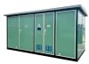
A switchboard, also known as a distribution box or substation, is a core terminal device in a low-voltage power distribution system (typically ≤1000 V AC). It is responsible for the safe, orderly, and controllable distribution of electrical energy from the upstream power source (such as a transformer or main distribution cabinet) to each electrical circuit.
It is widely used in residential, commercial buildings, industrial plants, and infrastructure projects, serving as a crucial safeguard for personal safety, reliable equipment operation, and power quality.
Standard definition(IEC 61439-1):
“A switchboard is a combination of one or more switching devices, protection devices, control devices and busbars, used for power distribution, circuit protection and operation control.”
The Core Function of The Power Distribution Cabinet
Power distribution
- Distribute the main incoming current to multiple outgoing circuits according to functional areas (lighting, sockets, air conditioning, power, etc.)
- Supports flexible expansion to meet future load growth needs
Circuit protection
Integrates miniature circuit breakers (MCBs), residual current devices (RCDs/RCBOs), etc., providing:
- Overload protection (prevents conductor overheating)
- Short circuit protection (quickly interrupts fault current)
- Leakage current protection (prevents electric shock, ≤30 mA)
Operation and Isolation
- Provides a visible break or clear open/close indication for safe isolation during maintenance
- Supports manual/automatic control (e.g., remote start/stop via contactor)
Monitoring and Management
The distribution cabinet integrates power metering, current/voltage monitoring, and communication modules, supporting energy management systems.
Main types of switchboards
Classified by application scenario
| Type | Full Name | American English Description (natural phrasing) | Typical Applications |
| Consumer Unit | Consumer Unit | A compact residential load center that typically combines miniature circuit breakers (MCBs) and RCD/GFCI-type protection in a plastic enclosure. | Homes, apartments, condos |
| MDB | Main Distribution Board (MDB) | The main switchboard for a facility—built for high current (typically 630A and up), usually metal-enclosed, feeding multiple downstream circuits/boards. | Industrial plants, data centers, shopping malls |
| SDB | Sub-Distribution Board (SDB) | A downstream distribution panel fed from the MDB, serving a specific area (like a floor, zone, or workshop) with localized circuit protection. | Multi-story buildings, large factories |
| MCC | Motor Control Center (MCC) | A centralized lineup that groups motor starters and controls—contactors, overload relays, and often soft starters or VFDs—for motor-driven equipment. | Pump stations, production lines, process facilities |
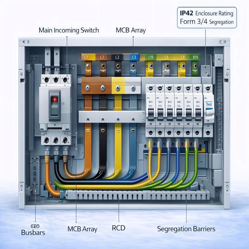
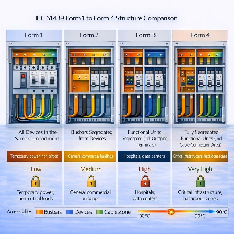
Classification by structure and safety level(IEC 61439)
| Form | Description (American English) | Safety Level | EPC-Recommended Use Cases |
| Form 1 | All components are installed within a single common compartment with no internal separation. | Low | Temporary power setups, non-critical loads |
| Form 2 | Busbars are separated from functional units, but devices share a common compartment. | Medium | General commercial buildings |
| Form 3 | Each functional unit is housed in its own compartment, including the outgoing terminals. | High | Hospitals, data centers |
| Form 4 | Complete separation of each functional unit, including the cable termination area, providing maximum isolation. | Very High | Critical infrastructure, hazardous or explosion-prone areas |
Core Components and Voltage Distribution Principles
Key internal components
| Component | Function | Key Selection Criteria (American English) |
| Main Switch | Turns the entire distribution board (DB) on/off (isolates the board). | Rated current ≥ 1.25 × the total calculated load. |
| MCB (Miniature Circuit Breaker) | Provides overload and short-circuit protection for an individual branch circuit. | Choose the right trip curve: Curve C for typical loads (lighting/general circuits), Curve D for high inrush loads (motors/transformers). |
| RCD / RCBO | Provides ground-fault (leakage) protection (typically 30 mA or 300 mA). | 30 mA for personnel protection; 300 mA for fire protection (upstream/selective applications). |
| Busbar | Main power distribution backbone inside the panel. | Size copper busbar cross-section based on ampacity; keep temperature rise ≤ 70 K. |
| Neutral & Ground Bar | Common termination points for neutrals and equipment grounds. | Must be separate, mechanically secure, and solidly bonded to ground (target R < 1 Ω). |
Voltage distribution and imbalance problems
In a three-phase system, the busbar (DB) distributes 400 V (line voltage) to each single phase (230 V) or three-phase circuit via a three-phase busbar. If the three-phase load is severely unbalanced, it will result in:
- Excessive neutral current (possibly greater than phase current)
- Decreased transformer efficiency and increased heat generation
- Voltage deviation (higher voltage in lightly loaded phases and lower voltage in heavily loaded phases)

Typical Engineering Application Scenarios
| Scenario | Required Configuration | Technical Highlights |
| Data Center IT White Space | MDB + SDB, Form 4 segregation, Class A fire-rated materials | Supports hot-swappable PDUs and integrates power quality monitoring. |
| Hospital Operating Room | Dual-source distribution board + ATS, medical-grade isolation transformer | Uses an ungrounded (IT) system,ground faults trigger an alarm instead of tripping the circuit. |
| Industrial Automation Line | MCC + intelligent motor protection relays | Supports PROFIBUS/Modbus communications and enables remote diagnostics. |
| Green Building | Smart distribution board + submetering | Integrates with the BMS to support energy optimization and better consumption visibility. |
Conclusion
Although the switchboard (DB) may seem simple, it is the “nerve center” of a low-voltage power distribution system. For engineers and EPC teams, accurately selecting the type, partitioning, protection devices, and intelligence level based on functional requirements is key to achieving the optimal balance between safety, reliability, cost, and future scalability.

Appendix: Commonly Used Standards
- IEC 61439-1/-2: Low-voltage switchgear and controlgear assemblies
- GB 7251.1: Low-voltage switchgear and controlgear assemblies – Part 1
- BS 7671 (IET Wiring Regulations): British Electrical Installation Standards
FAQ
1.What is the essential difference between MDB and SDB?
- MDB: Directly connected to the secondary side of the transformer or the upstream power supply, bearing the total load of the entire station, typically equipped with a large-capacity frame circuit breaker (ACB) or molded case circuit breaker (MCCB)
- SDB (Distribution Board): Powered by the MDB, serving a local area (such as a floor or a workshop), equipped with an MCB/RCD
2.Why must residential DBs use 30 mA RCDs?
According to IEC 60364-4-41, 30 mA is the threshold for preventing ventricular fibrillation. When a person comes into contact with a live conductor, if the leakage current is >30 mA and the duration is >40 ms, it may cause fatal electric shock. A 30 mA RCD can cut off the power supply within 20–40 ms, significantly improving personal safety.
3.What are the actual operational differences between Form 3 and Form 4?
- Form 3: Individual circuit MCBs can be inspected, but the cable connection terminals remain energized
- Form 4: Each circuit is fully isolated, including the cable connection area, allowing replacement of outgoing cables without power interruption
4.Can the neutral (N) wire in the DB be shared with the protective earth (PE) wire?
Absolutely not!
- Neutral (N) is the normal return path for load current, so it carries current during normal operation.
- Protective earth (PE) is a safety conductor that should carry no current under normal conditions and only conduct during a fault.
- If you combine N and PE (a TN-C arrangement), you can end up with energized equipment enclosures, which is a serious shock hazard and non-compliant with electrical safety requirements.
5.How to calculate the total load of the DB and the rated value of the main switch?
Calculate the total power after correction for the simultaneity factor of all circuits.(kW)
Converted to electric current: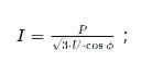
Rated current of main switch ≥ 1.25 × calculated current (considering future expansion and startup impact)
Example: Calculated current 400 A → Select 630 A for the main switch.

--- END ---
MV & LV Equipment Manufacturer · Wenzhou, China