- Telephone: +86-139-8977-9778
- Email: jack@toonice.com
- English
What Are Electrical Transformers and How Do They Work?
Jan 15,2026
Electrical transformers are among the most fundamental and critical static electrical devices in modern power transmission and distribution systems. They achieve efficient energy transfer between different voltage levels through the principle of electromagnetic induction, supporting the entire power network from power plants to industrial loads, commercial buildings, and even residential users.
What is a Power Transformer?
According to the IEC 60076 series standards, a power transformer is defined as:
“A static electromagnetic device that, using the principle of mutual inductance, transfers electrical energy between two or more windings with varying magnetic flux, typically used to change the values of AC voltage and current without changing the frequency.”
Its core value lies in
- Achieving efficient long-distance power transmission (reducing line losses through voltage boosting)
- Matching the voltage requirements of electrical equipment (ensuring safety and compatibility through voltage step-down)
- Providing electrical isolation (enhancing system safety and anti-interference capabilities)
In substations, industrial plants, data centers, and new energy power plants, transformers are indispensable energy “conversion interfaces.”
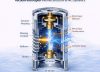
The Electromagnetic Principles Behind Voltage Transformation
Faraday’s Law of Electromagnetic Induction: The Physical Basis of Energy Transfer
The operation of a transformer is entirely based on Faraday’s law of electromagnetic induction and Lenz’s law. When an AC voltage V1 is applied to the primary winding, an alternating current I1 generates an alternating magnetic flux Φ in the core. This flux passes through the secondary winding, inducing an electromotive force E2, which drives the load current in a closed loop.
The voltage ratio of an ideal transformer is:
V2V1=N2N1
whereN1 and N2 are the number of turns in the primary and secondary windings, respectively. By precisely controlling the turns ratio, the desired voltage transformation can be achieved.

Actual Transformer vs. Ideal Model: Non-negligible Engineering Losses
Actual transformers exhibit various losses and non-ideal characteristics, directly affecting efficiency and temperature rise:
| Loss Type | Cause | Engineering Impact |
| Copper Loss ( I2R Loss) | Resistive heating in primary and secondary windings due to load current | Increases quadratically with load; directly affects efficiency, temperature rise, and cooling system design |
| Core (Iron) Loss | Hysteresis loss + eddy current loss in the laminated magnetic core | Present even at no-load; determines standby power consumption and long-term operating cost |
| Stray Loss | Eddy currents induced by leakage flux in tank walls, clamps, and other structural parts | Can cause localized overheating; mitigated through magnetic shielding or use of non-magnetic materials |
| Dielectric Loss | Energy dissipation in solid/liquid insulation under high electric stress | Affects partial discharge inception level and long-term insulation integrity; critical for HV transformers |
![]()
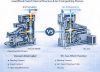
Main Types of Transformers
Transformer Classification by Cooling Method and Insulation Medium
| Type | Characteristics | Typical Applications |
| Oil-Immersed Transformer (OFAF/ONAN) | Excellent heat dissipation; high power rating (up to 1000+ MVA); strong overload capability | Transmission substations, large industrial facilities |
| Dry-Type Transformer (Cast Resin / VPI) | Oil-free; fire-resistant; maintenance-free | Commercial buildings, underground substations, data centers |
| Gas-Insulated Transformer (SF₆) | Compact design; sealed insulation system; reduced environmental footprint | Urban substations, space-constrained sites |
![]()
Critical Technical Parameters
| Parameter | Symbol | Typical Value / Requirement |
| Rated Power | SN | 50 kVA – 1000 MVA |
| Voltage Ratio | U1/U2 | e.g., 110/10.5 kV |
| Impedance Voltage | Uk | 6% – 12% |
| Vector Group | — | Dyn11, YNd1, etc. |
| Basic Insulation Level (BIL) | — | e.g., 450 kV (for 110 kV class) |
| Temperature Rise Limit | Δθ | ONAN: 65 K (top oil), 80 K (winding) |
Key Considerations in Project Implementation
Transportation and On-site Installation
- Large oil-fired transformers require verification of road turning radii, bridge load-bearing capacity, and hoisting space
- While dry-type transformers are lightweight, attention must be paid to their IP protection rating
- After installation, insulation resistance testing, turns ratio testing, DC resistance testing, and partial discharge testingare mandatory
Protection and Monitoring
- Mandatory: relay (for oil-fired transformers), temperature sensor (PT100/fiber optic)
- Recommended: Online monitoring system (DGA dissolved gas analysis, partial discharge, core grounding current)
Protection configuration must be coordinated with the time-current curve (TCC) of the upstream circuit breaker.
Trends: Intelligentization and Greening
- Intelligent Transformers: Integrating IoT sensors to support remote condition assessment
- Environmentally Friendly Insulation Medium: Natural esters (natural vegetable oils) and silicone oil replacing mineral oil
- High-Efficiency Energy-Saving Design: Meeting EU Tier 1/2 or China Energy Efficiency Standard 1 (GB 20052)
Conclusion
Although power transformers have no moving parts, they are the “silent guardians” of stable power grid operation. For engineers and EPC teams, going beyond the superficial understanding of “voltage transformation” and deeply understanding their electromagnetic nature, loss mechanisms, and full life-cycle management is essential to achieving a balance of safety, efficiency, compliance, and sustainability in projects.
In the context of energy transition and the construction of new power systems, transformers are evolving from traditional equipment into intelligent, green, and highly reliable energy nodes—this is both a challenge and an opportunity.
FAQ
- How does a transformer transmit electrical energy without any electrical connection?
Transformers operate on electromagnetic induction. An alternating current in the primary winding generates an alternating magnetic flux in the core, which induces an electromotive force in the secondary winding to supply the load. The absence of a conductive connection provides galvanic isolation, improving system safety, reducing common-mode interference, and supporting optimized grounding in power system design.
- Why can’t transformers be used in direct current (DC) systems?
Transformers require a changing magnetic flux to induce voltage. Direct current produces a constant magnetic field and cannot induce voltage in the secondary winding. When DC is applied to the primary, the low winding resistance allows excessive current to flow, leading to rapid overheating and possible insulation failure. Therefore, transformers are suitable only for AC systems.
- How to determine whether a transformer is a step-up or step-down transformer?
The key lies in the winding turns ratio (N1/N2 ):
Step-up transformer: Secondary side turns > Primary side turns (N2>N1), resulting in a higher output voltage. Commonly used at power plant outlets to reduce long-distance transmission losses;
Step-down transformer: Secondary side turns < Primary side turns (N2<N1 ), resulting in a lower output voltage. Widely used in power distribution systems to meet the voltage requirements of industrial or residential equipment.
- What are the main losses in a transformer? How do they affect efficiency?
Actual transformers exhibit two types of core losses:
No-load loss (iron loss): Caused by hysteresis and eddy current effects in the iron core, it exists even without load and determines standby energy consumption.
Load loss (copper loss + stray loss):Caused by winding resistance (I2R ) and eddy currents induced in structural components by magnetic leakage, it rises significantly with the increase of load.
The overall efficiency is:
η=Pout+Pcore+PcopperPout
Large power transformers typically have efficiencies >99%, but even small losses can lead to considerable energy consumption over long-term operation.
- How to choose between dry-type and oil-immersed transformers?
The choice depends on the application scenario and engineering constraints:
| Criteria | Oil-Immersed Transformer | Dry-Type Transformer |
| Cooling Capacity | Excellent; suitable for high ratings (>10 MVA) | Limited; typically ≤2.5 MVA |
| Fire Safety | Requires oil containment, firewalls; not suitable for indoor/underground installations | Oil-free and flame-retardant; approved for commercial buildings, hospitals, data centers |
| Maintenance | Requires periodic oil sampling, filtration, and testing | Virtually maintenance-free, but requires dust and moisture protection |
| Environmental Impact | Risk of oil leakage; disposal of mineral oil at end-of-life | Eco-friendly; complies with green building standards |
| Initial Cost | Lower | Higher |
- What does the “Connection Group” (e.g., Dyn11) on the transformer nameplate represent? Why is it important?
The “Connection Group” indicates the connection method and phase relationship between the high-voltage and low-voltage windings. For example:
D: High-voltage side delta connection (Delta)
y: Low-voltage side star connection (Wye)
n: Neutral point lead-out
11: Low-voltage side line voltage lags the high-voltage side by 30° (i.e., at the 11 o’clock position)
--- END ---
Let’s Get Started
Providing you with the most trusted energy solutions in an unpredictable world.
Contact UsRequest an Insurance Quote

Our Products
As a trusted manufacturer, we provide advanced equipment that supports the digital transformation and sustainability of the electrical grid.
Our carefully crafted product range meets the unique needs of different countries and clients.
More Products
