- Telephone: +86-139-8977-9778
- Email: jack@toonice.com
- English
What Is an Electrical Substation and How Does It Work?
Feb 05,2026
In modern power transmission and distribution systems, electrical substations serve as core hubs. They connect power generation and end users. Substations handle voltage transformation, power flow control, fault isolation, and system protection.
Definition and Core Functions of Substations
According to IEC 61936-1 and GB/T 50062, a substation is defined as:
“A power facility consisting of transformers, switchgear, busbars, protection and control devices, grounding systems, and auxiliary facilities, used to realize the reception, transformation, distribution, and control of electrical energy.”
Refer to the table below to understand its core functions.
| Function Category | Technical Implementation | Engineering Significance |
| Voltage Transformation | Power transformers realize high voltage and medium voltage/low voltage conversion | Reduce transmission losses and match load requirements |
| System Sectionalization and Isolation | Circuit breakers (CB), disconnectors (DS), earthing switches (ES) | Support maintenance and limit fault scope |
| Relay Protection and Automation | Microcomputer protection devices, SCADA, IEDs (Intelligent Electronic Devices) | Quickly clear faults and improve N-1/N-2 reliability |
| Reactive Power Compensation and Power Quality Management | Shunt capacitor banks, SVG, filters | Meet the requirement of power factor ≥ 0.9 (GB/T 12325) |
| Earthing and Lightning Protection | Ground grids (Ground Grid), surge arresters (Surge Arrester) | Ensure personal safety and suppress switching overvoltage |
Electrical Principles Behind Voltage Transformation
Why are Multi-Stage Voltage Transformation Needed?
Power systems employ a “high-voltage long-distance transmission + step-down distribution” architecture, theoretically based on Joule’s law( Ploss=I2RPloss=I2R)
When the transmitted power P is fixed, increasing the voltage V can significantly reduce the current I/, thereby reducing line losses.
![]()
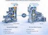
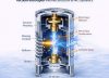
Transformer Working Principle: Electromagnetic Induction and Flux Coupling
The main transformer operates based on Faraday’s law of electromagnetic induction:
V1/V2=N1/N2V1/V2=N1/N2
where N1,N2 are the number of turns in the primary/secondary windings. Energy is efficiently transferred through the core magnetic circuit (efficiency typically >99%).
![]()
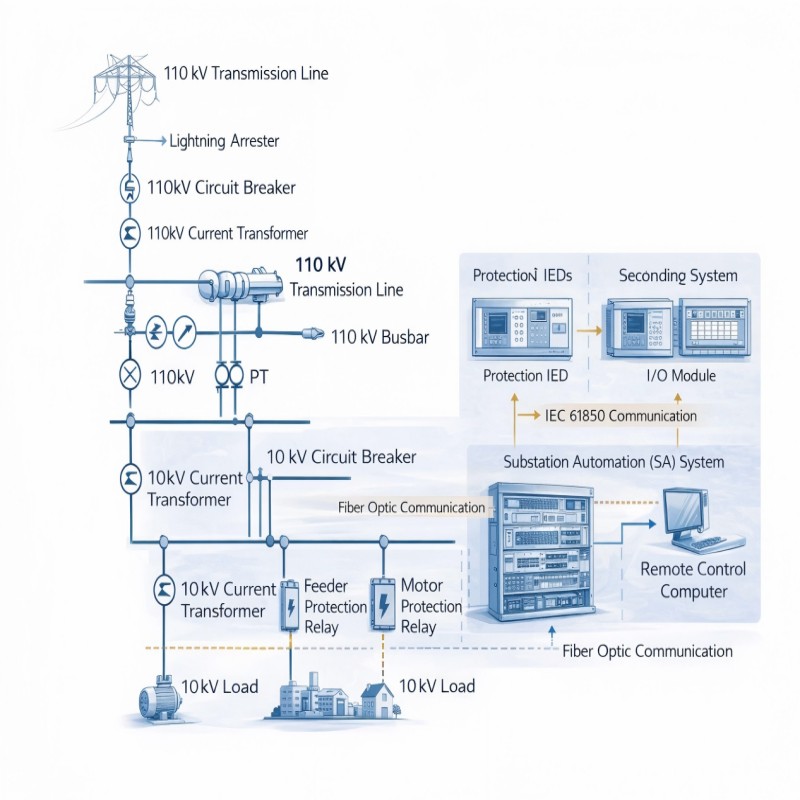
Typical Substation Architecture and Key Points for Equipment Selection
Substation Types Classified by Function
| Type | Voltage Level | Typical Configuration | EPC Focus Points |
| Transmission Substation | 220 kV and above | GIS/HGIS, large-capacity power transformers (≥ 180 MVA) | System short-circuit capacity, N-1 verification, footprint optimization |
| Regional Distribution Substation | 110/35 kV | AIS or compact GIS, double busbar with sectionalization | Load forecasting, expansion reservation, automation interface |
| Customer-Specific Substation | 10/20 kV | Compact substations (Compact Substation) or indoor substations | Power supply agreement (PCC point), harmonic assessment, metering accuracy |
| New Energy Collection Station | 35 kV (Wind/PV) | SVG + collection lines + step-up transformers | Low Voltage Ride-Through (LVRT), reactive power response time |
Key Equipment Selection Technical Parameters
Taking 110 kV GIS as an example
| Equipment | Key Parameters | Standard Reference |
| SF₆ Circuit Breaker | Rated breaking current ≥ 40 kA, mechanical life ≥ 10,000 operations | IEC 62271-100 |
| Current Transformer (CT) | Accuracy class 0.2S/5P20, transient coefficient ≥ 2.0 | GB/T 20840.2 |
| Voltage Transformer (VT) | Accuracy class 0.2/3P, residual voltage winding | IEC 61869-3 |
| Power Transformer | Impedance voltage 10–12%, ONAN/ONAF cooling | GB/T 6451 |

Key Technical Challenges in Project Implementation
Grounding System Design
- Grounding resistance must meet the requirement R≤2000IgR≤Ig2000 (GB/T 50065), Where IgIg is the ground fault current
- Step voltage and contact voltage simulation is required (e.g., using CDEGS software)
- In areas with high soil resistivity, resistance-reducing agents or deep well grounding are required
Relay Protection Setting Coordination
- Main transformer differential protection, backup overcurrent, and zero-sequence protection must be coordinated with the time-current characteristics (TCC) of the upstream/downstream protection
- New energy access requires the addition of frequency/voltage anomaly protection logic
Digitalization and Intelligentization Trends
- Promote the IEC 61850 standard and achieve GOOSE/SV communication
- Deploy online monitoring systems (DGA, partial discharge, iron core grounding current)
- Support remote operation and maintenance and digital twin integration
Substation application scenarios
| Application Type | Typical Scenarios |
Voltage Level (Common) |
Main Function |
| Regional Substation | Urban power supply, industrial parks | 110/220 kV → 10/35 kV | Step down high voltage to medium voltage for distribution network |
| Terminal Substation | Malls, hospitals, residential areas | 10/35 kV → 400 V | Provide low-voltage power to end users |
| PV/Wind Step-up Station | Wind farms, photovoltaic power stations | 0.69/35 kV → 110 kV | Collect renewable energy and step up for grid connection |
| Rail Transit Substation | Metro, high-speed rail traction systems | 110/35 kV → 750 V DC / 25 kV AC | Supply dedicated traction power for trains |
Conclusion
Driven by the “dual carbon” goal, substations are evolving from traditional power nodes to energy routers. For engineers and EPC teams, it is not only necessary to master classic electrical design but also to integrate power electronics, communication protocols, and system simulation capabilities.
In the future, substations will deeply integrate new technologies such as energy storage, flexible DC transmission, and virtual power plants, becoming a key carrier for building new power systems.
Appendix: Commonly Used Standards and Specifications
IEC 61936-1:2020: Design of AC Installations for High Voltage Substations
GB 50059-201: Design Specification for 35kV~110kV Substations
IEEE C37.118: Standard for Synchronous Phasor Measurement
DL/T 5103-2019: Design Code for 35kV~110kV Unmanned Substations
Frequently Asked Questions (FAQ)
- What does a substation do?
Its main functions are to transform voltage, distribute electrical energy, and provide protection in the event of grid failures.
- Are substations dangerous?
Substations are very safe when designed, constructed, and maintained according to regulations. There are strict national safety standards and protective measures.
- Can substations explode?
Extremely rare. Modern protection systems effectively prevent serious accidents. Most accidents are caused by external factors such as extreme weather or traffic accidents.
- How far should a residence or building be from a substation?
Regulations vary by region, but a safe distance of 3–10 meters is generally required. Consult your local power supply department or planning agency for specific advice.
- Does a substation produce radiation?
It produces extremely low-frequency electromagnetic fields (EMF), but the intensity is comparable to that of household appliances. Authoritative organizations such as the World Health Organization confirm that there is no health risk at normal exposure levels.
<p “>Box Type Substation Compact Power Distribution Solution
America Type Substation Solutions – Toonice
Substation Solutions: Toonice Power Equipment
--- END ---
Let’s Get Started
Providing you with the most trusted energy solutions in an unpredictable world.
Contact UsRequest an Insurance Quote

Our Products
As a trusted manufacturer, we provide advanced equipment that supports the digital transformation and sustainability of the electrical grid.
Our carefully crafted product range meets the unique needs of different countries and clients.
More Products
